Configuring a Ruida
When purchasing a laser with a DSP controller installed, the factory making the machine configures the laser controller for you to tell the controller how fast and in what directions to move, where the homing switches are, and so on.
If you are installing a new controller into a machine, you will need to perform the configuration that is normally done for you by the factory.
A somewhat common mistake for new users is doing a 'factory reset' of their controller - this resets it to the stock configuration supplied by Ruida, not the configuration applied by the company that set up your laser, so it's not recommended to do this. Chances are you already have, which is why you're here.
Ruida Machine Settings in LightBurn
With the laser connected to your computer, go to the bottom of the Edit menu and click Machine Settings. LightBurn will open the Machine Settings window and read the configuration from your controller. You should see this screen:
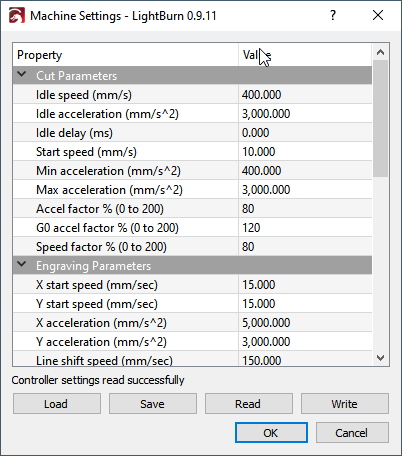
The top section of the list is referred to as user settings - these are settings that are intended to be tunable by the user if necessary. The lower section, under 'Vendor Settings' are things usually configured for you by the factory and should only be changed if you have a good reason for doing so.
It's also a good idea to back up the initial settings before you change them, so you can go back to what you had if you make a mistake and can't remember what you did.
The 'Read' button tells LightBurn to read the settings from the controller (this happens automatically when you open the Machine Settings window). The 'Save' button will write all settings to a file. 'Load' will read settings from a file back into memory. 'Write' commits the settings in LightBurn back to your controller.
In the bottom of the Machine Settings window is a heading called Vendor Settings. Click it to 'unroll it' and you'll see something like this:
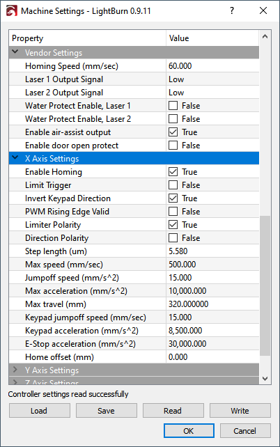
The first section is general configuration, and then there are settings that are specific to each axis, followed by a Laser section, for configuration specific to the laser type.
Homing, Directions, and Travel
A DSP laser will have homing switches - one on each axis. They might be physical lever-type micro switches, optical beam-break switches, or inductive proximity sensors. Locate the switch at the end of the X axis, and the one for the Y axis. Note that the Ruida homes using the X- and Y- limit switches.
When you power up the laser, the first thing it will do is move toward the corner it thinks those switches are at to home itself. If it's moving in in the wrong direction, you'll have to hit the ESC button on the controller itself to stop it.
Bring up Machine Settings in LightBurn, and go to the Vendor settings section at the bottom, and open the X axis and Y axis Settings. Near the top of each will be three check boxes:
-
Invert Keypad Direction
-
Limiter Polarity
-
Direction Polarity
The first (keypad direction) controls which way the arrow buttons move the laser. The second (limiter polarity) tells the controller whether the limit switch triggers high (normally open) or low (normally closed) when contacted, and the 3rd (direction polarity) controls which way the motor moves in general.
There are only 4 possible combinations of "limiter polarity" and "direction polarity" for each axis. I can't tell you which is the correct combination, but change those settings for the X axis until it moves properly when you power the machine, then do the Y axis. Once these are set, the next steps are easier.
When the limiter and direction settings are correct, check that the keypad arrows on the machine are moving the laser in the correct direction. If not, toggle the 'Invert Keypad Direction' button for whichever axis is wrong.
You will also need to set the 'Max Travel' value for the X and Y axis - these numbers dictate the length of each axis, and together define the size of the work area of the machine.
Step Length Calibration
The next part is figuring out how far the laser moves when you tell it to, and how far off it is. The controller needs to know how far a single step moves when it sends a step pulse to the motors so it can translate real measurements into the proper number of steps.
Rough Calibration
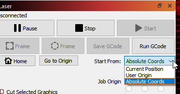
In LightBurn, set the 'Start From' setting in the Laser window to Absolute Coords, like this:
Then draw a small rectangle at the origin. Start with 10 x 10 or 20 x 20 mm, like this:
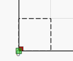
Note that your origin corner might be in a different spot than mine - you should set it in the device settings to match the origin corner of the machine.
Now, use the 'Frame" button (shown above, near the 'Start From' setting) and see how big it frames. If it's barely moving, your step size is too big (the controller thinks it is moving more than it is). If it moves way too far, the step size is too small (the controller thinks it has to take lots more steps than necessary).
This part is just doing rough adjustment - it's not accurate at all, but you need to get into the right ballpark before doing the next part.
In the Machine Settings again, in the settings for the X and Y axis, are values called 'Step Length' Adjust those according to what I said above - If the controller doesn't move enough by half, cut the step length in half. If it moves twice as far as it should, double the step length. Frame again, and iterate until the size of what you've drawn and the size the laser frames is reasonably close.
Final Calibration
Now, draw a box similar to the original, but make it 100 x 100, or 200 x 200 (mm), set the Min and Max power low to start, but high enough to make a mark, and run the job it on a piece of scrap material. Measure the result as accurately as you can.
This time, actually do the real math with the step size:
- New Step Size = (Current Step Size * Measured Length) / Requested Length
If the controller complains about 'water protect', you can disable the water protect setting in the machine settings. Ditto for the door protect (it's the lid open switch). If you have a flow meter, you should have it hooked up so you know you have water running through the tube, and have the water protect enabled.
As you are dialing in the above settings, if the steppers skip or make buzzing sounds, you might need to reduce the Idle Acceleration or Idle Speed settings near the top. Those things will require tuning with some trial and error.
Fixing Skewed Engraving
An occasional problem with new setups, and sometimes even existing machines, is lines cutting correctly, but engravings coming out slanted or skewed, like this:

If your output looks like this, you likely have your motor pulse step polarity set incorrectly. On Ruida controllers, there’s a setting called ‘PWM Rising Edge Valid’ that you can change for each axis that tells the controller whether the rising edge or falling edge of a step pulse is what the motor driver is looking for. Toggling this may fix skewed engraving.
The fix is relatively simple. In Edit > Machine Settings, look in the X & Y axis motor settings section at the bottom, and look for the value of 'PWM Rising Edge Valid' on the X axis. Change that - if's it's checked, un-check it, or vice versa. Then, copy the new setting over to the Y axis as well.
What is this setting and why does it matter?
A step pulse is a transition from low to high, or high to low. The controller will hold the line low, and pulse it high, or hold the line high, and pulse it low. The transition itself is what matters, and motor drivers will either look for a transition from low to high (rising edge) or high to low (falling edge) to accept as a ‘Step’.
If the laser controller believes that the motor driver is looking for the leading edge signal (when it transitions from low to high), it will pulse the line, and could change the direction line immediately after that. If the motor driver is waiting for the falling edge, it will see the direction change BEFORE the falling edge of the pulse, meaning that it will change direction one step too soon.
[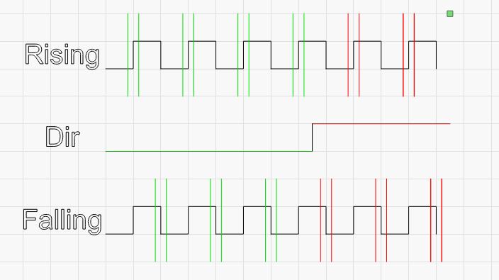
In the image above, the upper line of steps is interpreted as 4 steps in one direction, then two in the other. The lower line is interpreted as 3 and 3, and the only difference is which side of the step signal the driver is looking for.
Start & End Delay
This features adds in a start/stop delay to allow the laser to enable any systems it enables itself when starting a job. This gives, for example, fans time to get to speed or evacuate the air in the laser before stopping when done.