Common GRBL/GCode Setups
Most GCode-based lasers are pre-configured to work with LightBurn, but if you have a less common machine like a Shapeoko, EleksMaker, X-Carve, or Acro system, you might need to make some simple changes to get the most from LightBurn.
Quick Reference
- You might need to adjust your spindle max RPM value (
$30) to match the LightBurn default (1000) or vice versa. The value in LightBurn is called "S-Value Max" in Device Settings. - You might need to enable "Laser Mode" if you have GRBL 1.1f or later (
$32=1) - If you have an older version of GRBL (prior to 1.1f) upgrading the firmware is highly recommended, as Laser Mode also prevents the machine from pausing with every power change. The pause, which happens on older versions, or when not using Laser Mode, will cause excessive burn spots when engraving images.
- If your machine uses negative workspace coordinates you'll need to apply a workspace offset (
G10 L2 P1 xx yy). - Set your machine status reporting to be relative to the workspace origin, not the machine origin (
$10=0). - Make sure the controller is reporting positions in mm, as expected by LightBurn (
$13=0) - If your machine does not have homing switches (also called limit switches) you will need to home it manually if you want to use Absolute Coords or User Origin modes
GRBL Flavors
GRBL firmware was originally designed for CNC machines and 3D printers, with laser support added more recently. It is highly configurable, and this is both a blessing and a curse. The "standard" way a CNC machine is configured is somewhat different from the way laser machines often are. Luckily this is easy to change, and easy to switch from one to the other.
More recent versions of GRBL (1.1f and up) support two laser-oriented features. The first is Laser Mode, enabled by setting $32=1 in the firmware settings. Laser mode eliminates the pauses that happen when changing power output, because GRBL knows it's controlling a laser which reacts instantly, instead of waiting for a spindle to change RPM.
The second is a feature called variable power mode, or the M4 command. In this mode, GRBL adjusts the laser power as the machine speeds up and slows down, making for very consistent cutting and marking. Older versions of GRBL do not have this feature, and simply run the laser at a constant power output for the duration of a cut. Since the machine needs to slow down to take sharp corners, this means corners get over-burnt, while long straight lines end up lighter. This also has the benefit that when the laser comes to a complete stop, the beam turns off (zero speed equals zero power), meaning that pausing a job automatically turns off the laser. This is not always true with other versions of GRBL.
If you aren't already running GRBL 1.1f (or later) on your controller, we highly recommend it for laser use. If this isn't an option, that's ok, but your results won't be as good, and pausing the laser runs the risk of leaving the beam on and ruining the job.
Getting Machine Settings
Many GRBL based machines allow the settings of the machine to be easily exported or viewed. For advanced configuration like adding limit switches, updating firmware, or setting up a new controller, you'll need to interact with these values. You can do this in LightBurn by using the Console window or the Machine Settings window to copy, update, or reset your machine settings.
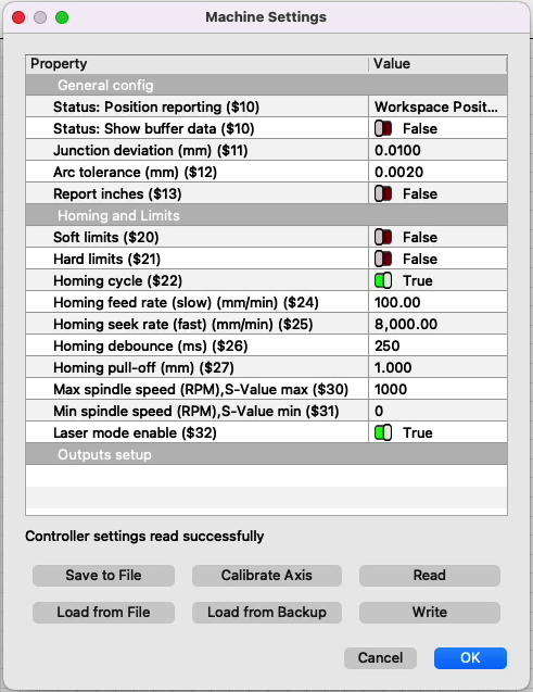
The Machine Settings window provides you with a formatted table with the parameters labeled. You can also export these settings to a file for later restoration, like we did in our GRBL flashing guide.
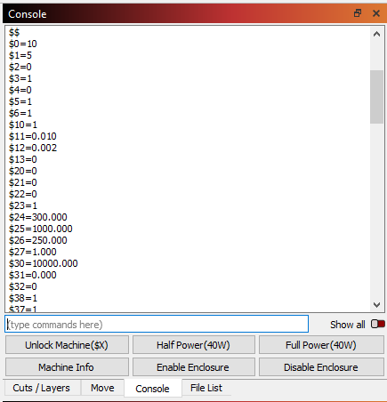
In the Console, enter $$ to have the controller return the machine's configuration. This will show the settings in plain text, requiring more familiarity with what each command means but allowing you to view the configuration directly, without any chance of mislabeling based on custom vendor configurations.
Shapeoko
Shapeoko machines typically use GRBL 1.1f, as do newer X-Carve and some other systems, but as they are designed as CNC machines, they are typically configured for negative workspace coordinates. LightBurn doesn't directly support negative workspace coordinates, but you can use a Shapeoko in LightBurn with a workspace offset. Please see the directions in Negative Coordinate Machines for directions to set a workspace offset, clear the offset to use the machine in CNC mode, and create macros to switch modes quickly.
You can set these commands up as macro buttons in the LightBurn console window. Enter the first command into a macro and call it "Use Laser", and enter the second command into a different macro and call it "Use CNC". When you want to use your laser, click the "Use Laser" macro button, and when you're done and want to switch back to CNC, click the "Use CNC" button.
After setting this, you will also need to make sure your machine is reporting coordinates relative to this workspace origin, instead of the absolute machine zero. Do this by entering $10=0 in the console.
X-Carve
X-Carve machines sold prior to January 2018 generally run an older flavor of GRBL (1.0c) which does not support the variable power (M4) command, meaning you'll need to use the GRBL-M3 device in LightBurn. Machines sold after that date use GRBL 1.1f, and will work with the standard GRBL device in LightBurn if the following settings commands are entered in the console:
$30=1000
$32=1
These two lines:
- Set the spindle max value ($30) to match LightBurn and GRBL's default setting (1000)
- Enable laser mode ($32=1)
Other Machines
If you aren't sure how to configure your machine, the following steps will help you figure it out.
Figure out which firmware you're running
In LightBurn, when you first connect to the machine the console will typically show a 'hello' message from the controller. For Smoothieware boards it is just "Smoothie". For GRBL, it will be "GRBL 1.1f [$ for help]" or similar - this tells you it's GRBL, and which version. Machines using GRBL 1.1f or later will support the M4 variable power command, and just use the "GRBL" driver in LightBurn. GRBL 1.1e or older (GRBL 1.0, GRBL 0.9, etc) must use the GRBL-M3 device in LightBurn.
Find the machine origin and coordinate direction
- Home the machine by pressing the Home button (
 ) in the Move window.
 - In the console window, type
G0 X0 Y0and press Enter. This will command your machine to head toward its origin position - the location represented by (0, 0) in the machine's coordinate system. This is not always the same as the home position. The origin is usually either the front left corner or the rear right corner of the machine, but can be a different corner or the center of the work area. If your machine moved to the center, skip to Center Origin Machines for more information. - After the machine has stopped moving from the previous command, type
G0 X10 Y10and press Enter. If your machine moves 10 mm into the work area on both axes, your machine uses positive workspace coordinates. You can set the origin in LightBurn to match the machine origin you found in step 2. If your machine bumped the rails, it uses negative coordinates. Please see Negative Coordinate Machines for more information.
Negative Coordinate Machines
LightBurn expects positive workspace coordinates. If your machine is configured to use negative workspace coordinates, you can set a workspace offset to enable compatibility with LightBurn. If you are switching between LightBurn and CNC software that expects a negative coordinate system, you can clear the workspace offset. You can also set macros to toggle between the two modes.
Set A Workspace Offset
In the console, enter G10 L2 P1 X-WIDTH Y-HEIGHT and hit Enter. Replace WIDTH and HEIGHT with the actual X and Y travel distances of your machine. Set your machine to use workspace coordinates with the $10=0 command.
Example: G10 L2 P1 X-310 Y-180 Enter
Clear a Workspace Offset
In the console, enter G10 L2 P1 X0 Y0. This is generally only required if switching between using your machine as a laser (with an offset) and as a CNC machine in software that expects negative coordinates.
Detailed Explanation.
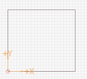
This image shows the origin at the front left, with positive X values moving to the right, and positive Y values heading to the rear of the machine.
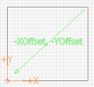
A negative workspace system looks like this:
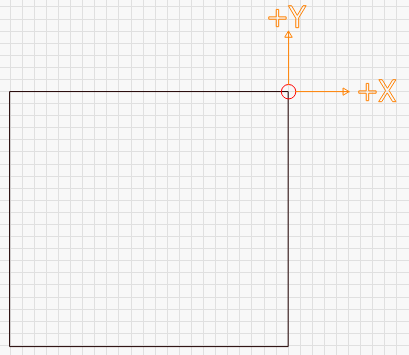
In this image, the origin is at the rear right of the machine. The X and Y directions are the same as before, but now you would need to use negative numbers to move into the work area.
You'll need to know the total distance your machine can travel in both axis. For a Shapeoko XXL, for example, it's 812 mm in X and Y. For a 1000 mm 2nd Generation X-Carve, it's 750 mm in X and Y - note the difference between overall size and travel distance. By applying a workspace offset that is the size of your machine area, you can shift the offset to the opposite corner, like this:
Entering G10 L2 P1 X-812 Y-812 means set an offset (G10 L2) in the first coordinate system (P1) with a distance of -812 mm in each direction (X-812 Y-812).
If you enable a workspace offset, you will also need to make GRBL report its location relative to this shifted origin, instead of in "machine space", by setting $10=0. Some systems, like Easel or Carbide Motion, may need a different value, so it's a good idea to make a note of the existing setting.
Set Macros
For a one click way to set or clear workspace coordinates, you can store these commands in the macro buttons in the console window.
- Right click one of the buttons at the bottom of the console window
- Enter the command you want to save in the text box that pops up
- Set the button label to something easily recognizable, such as "Use Laser" or "Use CNC"
- Press OK to save the settings
Once the macro is saved, you can use the command by pressing the appropriate button.
Center Origin Machines
Some systems have their origin in the center of the workspace. To confirm that this is the case, after homing your machine enter G0 X0 Y0 in the console and press Enter. This command says "rapid move to coordinate 0,0". If your machine travels to the center of the workspace, it's configured for a center origin.
A center origin machine requires a workspace offset similar to what's described in Negative Coordinate Machines, but the offset should be half the travel distance. For instance, a machine with a travel distance of 500 mm x 500 mm and a center origin would require G10 L2 P1 X-250 Y-250.
Machines without homing sensors / limit switches
If your machine does not have homing switches (also called limit switches) you will need to home it manually if you want to use Absolute Coords or User Origin modes. There are two ways to do this:
- With the machine off, manually move the laser head to the origin position (usually front-left), then power up the machine. Until you tell it otherwise, the power-on location of the controller is treated as the zero position.
- With the machine powered, jog the laser head to the origin position. In the console window, type:
G92 X0 Y0and press Enter. TheG92command tells GRBL to set the current location as the specified coordinate, so you're telling the machine "this is zero". You will also need to set$10=0for this to work correctly.
If you use the second option frequently, you may want to save the command as a macro.
xTool Wi-Fi Upload
We do not currently (as of LightBurn 1.5) support uploading GCode to the xTool family of lasers via Wi-Fi. The upload mechanism is significantly different from the currently supported methods, and that development hasn't yet been completed. Thank you for understanding.